
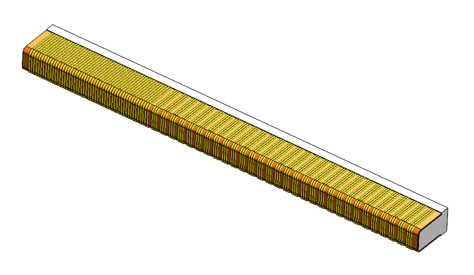
When designing an application around a conductive elastomeric connector, one important consideration is the number of conductive wires that make contact with each PCB pad.
Unlike a traditional connector that uses an individual metal contact for each circuit, a Z-Axis elastomeric connector contains many closely spaced conductive elements embedded within an insulating silicone body. When the connector is compressed between two mating surfaces, these conductive elements create electrical paths between the corresponding contact pads.
This raises an important design question:
How many conductive wires should contact each PCB pad?
Why Wire Count Matters
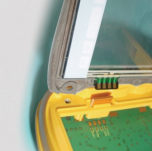
In most applications, multiple conductive wires should contact each pad.
Using multiple wires provides contact redundancy. Rather than relying on a single conductive element to complete the circuit, several independent conductive paths are available across the same pad.
For example, if a pad is contacted by four conductive wires, all four wires are electrically connected to the same pad and provide parallel conductive paths through the elastomer.
This can help provide:
- More consistent electrical contact
- Greater tolerance for PCB and assembly variation
- Improved reliability during compression
- Additional contact redundancy
- Lower effective contact resistance
For these reasons, maximizing the number of conductive wires per pad is generally beneficial when the available geometry allows it.
Is There a Minimum Number of Wires per Pad?
There is not one universal number that applies to every elastomeric connector application.
The appropriate wire count depends on several factors, including:
- PCB pad width
- Pad pitch and spacing
- Elastomer conductor pitch
- Alignment tolerance
- Compression
- Current requirements
- Signal frequency
- Mechanical tolerances of the assembly
As pad pitch becomes smaller, the number of conductive wires that can physically contact each pad also decreases.
A larger 1.00 mm pitch interface, for example, may allow several wires to contact each pad relatively easily. A fine-pitch 0.50 mm interface provides considerably less available pad width and may require fewer wires per contact.
The important consideration is not simply the nominal number of wires over the center of the pad. The design should also account for the expected worst-case alignment between the elastomer and PCB pads.
More Wires Provide More Design Margin
Consider a design where four conductive wires nominally contact each PCB pad.
If manufacturing or assembly tolerances cause the elastomer to shift slightly, the exact location of those wires relative to the pad will also change. A design with several wires per pad may still maintain multiple electrical paths despite this shift.
A design that relies on only one or two wires has less geometric margin.
This is why wire count should be evaluated together with pad spacing and alignment tolerance, rather than as an isolated specification.
The goal is to ensure that sufficient conductive wires remain completely within the intended contact area throughout the expected tolerance range.
Can Two Wires per Pad Work?
Yes.
Some fine-pitch applications may require a design with only two conductive wires per pad due to the available PCB geometry.
A two-wire design can be a practical solution when the pad width, conductor pitch, alignment, and mechanical tolerances are properly controlled. However, reducing the number of wires also reduces the amount of contact redundancy available.
For applications where two wires per pad are being considered, the complete tolerance stack should be reviewed to verify that both wires reliably remain within the intended pad area.
Electrical Requirements Also Matter
Mechanical geometry is only part of the equation.
The electrical requirements of the application should also be considered when determining an appropriate wire count.
For higher-current applications, additional conductive wires provide more parallel current paths through the connector. For high-frequency applications, the conductor arrangement, pad geometry, ground configuration, connector dimensions, and surrounding PCB structure may all influence signal performance.
As a result, the ideal configuration for a low-frequency control interface may be different from the ideal configuration for an RF or high-speed digital application.
General Design Recommendation
When space permits, Z-Axis generally recommends designing the interface so that multiple conductive wires contact each PCB pad.
More wires per pad provide additional redundancy and tolerance margin, but the highest possible wire count is not necessarily required for every application.
The correct design is ultimately a balance between:
Pad geometry + conductor pitch + alignment tolerance + compression + electrical requirements
For fine-pitch or space-constrained designs, a lower wire count may be appropriate when the complete interface is designed around it.
Designing an Elastomeric Connector Interface
The number of conductive wires per pad should ideally be considered early in the PCB and connector design process.
Z-Axis Connector Company can review PCB pad geometry, connector dimensions, compression, conductor pitch, and mechanical tolerances to help determine an appropriate configuration for a specific application.
For new designs, providing a PCB drawing, pad layout, or 3D model allows the complete contact interface to be evaluated before the assembly is finalized.