Design Guide & Form
Use the dropdown sections below to explore specific guidelines for connector geometry, housing features, and other design considerations.
Please complete the form at the bottom of the page with your specific requirements. Our team will use this information to provide a tailored solution for your design.
Design Recommendations
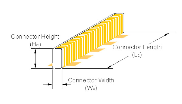
At Z-Axis Connector Company, each connector is customdesigned and manufactured to meet the specific needs of each customer’s application. In order to determine the overall connector dimensions specific to your application, the following design recommendations may be used in calculating the length (Lc), height (Hc) and width (Wc) of your elastomeric connector.
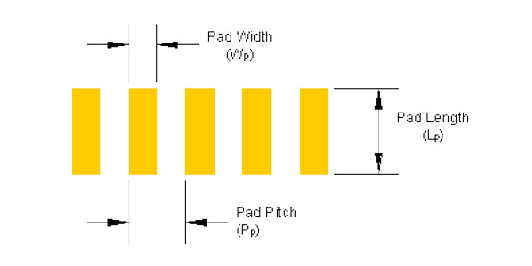
The length of the connector (Lc) is a function of the contact pad layout. To guarantee full coverage of the contact pads including any possible shifting, the connector length is generally .025” (0.64mm) greater than the distance from the edge of the first pad to the edge of the last pad.
Connector Length (Lc) = (N – 1) Pp + Wp + .040” (1.0mm) where N = the number of contact pads.
The most critical dimension with respect to connector performance is height (Hc). Deflection in the z-axis or the height direction is essential to the functionality of an elastomeric connector.
Too much deflection may create excessive forces that could result in bowing of the PCB while too little deflection could result in marginal contact that may not be reliable under certain conditions.
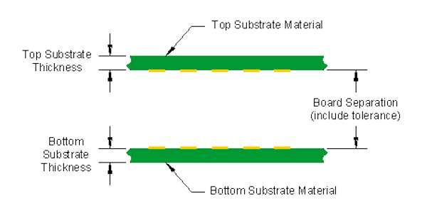
Therefore to provide reliable, consistent performance, the connector height must be carefully chosen and must take into account the board separation dimension as illustrated above. Z-Axis recommends that under worst case conditions, the connector is designed to allow for a minimum deflection equivalent to 5% of the connector height.
To do this, the largest possible board separation must be compared to the shortest possible connector (including tolerances). Typically, the tolerance for the height of the connector is +/- .005” (0.125mm). The following formula will determine the optimal connector height for your application.
Connector Height (Hc) = ((Board Separation + tolerance) / .95) + Connector Height Tolerance where .005” (0.125mm) is the default connector height tolerance.
When proper care is taken in determining the connector height, Z-Axis elastomeric connectors will offer consistent results even under conditions such as shock, vibration and environmental extremes.
The width of the connector (Wc) is a relative dimension and should be selected based on several criteria.
Reliability – To provide adequate contact area, the width of the connector must be large enough to guarantee that the connector will mate properly with the contact pads even under worst-case conditions. Therefore, the minimum recommended connector width is .020” (0.5mm).
Force – Although wider connectors include more conductive material, they also include additional silicone. Since silicone is not a compressible material, it must be displaced when the connector is assembled. Excessively wide connectors should be avoided to minimize the deflection forces of the connector.
Stability – Since the connector will be deflected when it is assembled, the ratio of connector height to width must not be too high to avoid buckling or folding of the connector. This may also be addressed with the connector housing design to provide proper support. In general, the following equation will offer acceptable width values based on a given connector height (Hc).
Connector Width (Wc) = Hc / 2.5 (may range from 1 to 5)
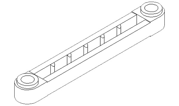
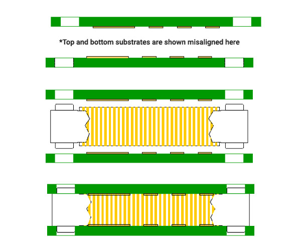
The connector housing may be a discrete piece as shown in the following illustrations, but ideally, these housing features and geometries are incorporated into the housing of the end product.
The housing for an elastomeric connector performs several functions and is capable of providing many benefits within the end unit. These advantageous characteristics include:
- Deflection stop – Flat lands at each end of the housing allow for very accurate control of the board separation within the system
- Connector support – Walls of the housing afford mechanical stability for the connector
- Captures connector – Ribs offer an interference fit that hold the connector in place during assembly
- Room for displacement – Space created by the ribs allocate volume for the silicone to fill as the connector is deflected during assembly
- Align mating substrates – Pins protruding from both sides of the connector provide accurate registration to increase reliability
- Facilitates clamping – Through holes in the alignment pins make it possible to fasten mating substrates within the same space allocated for the connector
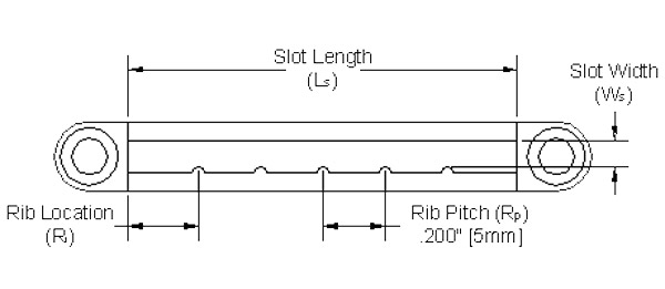
The length of the slot (Ls) that will house the elastomeric connector must allow for tolerances in the length of the connector and should therefore be slightly larger than the Connector Length (Lc). Under normal conditions, the slot is designed to be .010” (0.25mm) longer than the elastomer. Slot Length (Ls) = Lc + .010” (0.25mm)
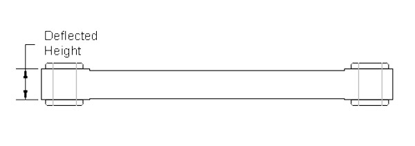
The connector housing may be used as a deflection stop for the mating substrates to accurately control deflection within the tolerance of the housing itself which is usually +/- .002” (0.05mm) or better. If this is possible, the slot height (Hs) will be equal to your desired board separation.
Slot Height (Hs) = Board Separation = Deflected Height
If it is not possible to take advantage of the housing as a deflection stop, the height of the slot must allow for all possible variations in board separation to avoid obstruction during assembly. Please note, even if the housing is not acting as a deflection stop, the slot height should be as tall as the system will allow providing maximum support for the connector while preventing an unnecessary fulcrum that may fold or pinch the connector between the housing and the mating substrate.
The slot width (Ws) is defined as the distance from the tip of the rib to the wall opposite it. A slight interference of .004” (0.1mm) will hold the connector in place while justifying it against the flat wall.
Slot Width (Ws) = Wc – .004” (0.1mm)
Ribs inside the slot of the housing are a critical component to the functionality of the connector. They provide many essential functions within the connector system, such as:
- Interference between the ribs and the connector captures the elastomer and holds it in place so that it acts as one component to simplify assembly.
- Locates the connector within the slot by repeatedly justifying the elastomer against the flat wall.
- Allows room for the connector to grow during assembly. Since the silicone in the connector does not compress, it acts like a balloon and requires extra space for its volume to displace and fill.
Number of ribs (Nr) = Ls/Rp
- Round Nr down to nearest integer for # of ribs
- Ls = Slot length
- Rp = Rib pitch = .2” (5mm)
Rib location (Rl) = (Ls – Rp(Nr – 1))/2
Rl is the location of the first rib from the edge of the slot
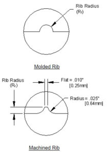
The radius of the ribs (Rr) is determined by the width of the connector. A larger radius creates a larger gap for the elastomer to fill when compressed. So, a wider connector will require a larger rib. Following is a table that details our recommendations for the rib radius based on given connector widths.
As a check of your housing design, it is always a good idea to compare the volume of the slot to the volume of the connector to assure that the connector has sufficient room to expand. The volume of the slot must be greater than the volume of the connector.
| Connector Width (Wc) | Rib Radius (Rr) |
| Wc < = .050” (1.3mm) | .015” (0.38mm) |
| .050” (1.3mm) < Wc < = .075” (1.9mm) | .020” (0.5mm) |
| .075” (1.9mm) < Wc < = .100” (2.5mm) | .025” (0.64mm) |
| .100” (2.5mm) < Wc | .030” (0.76mm) |
As a check of your housing design, it is always a good idea to compare the volume of the slot to the volume of the connector to assure that the connector has sufficient room to expand. The volume of the slot must be greater than the volume of the connector.
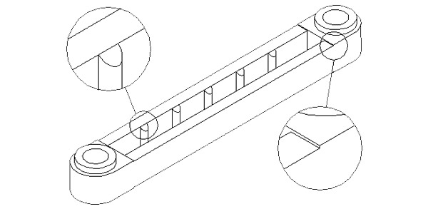
Chamfered lead-in eases assembly.
Alignment pin with through hole integrates substrate registration and clamping functions, maximizing reliability while conserving space.
Stepped housing provides clearance for contact pads and avoids a potential pinch point between the PCB and connector housing.
Design Considerations
One major benefit of elastomeric connectors is the fact that the connector itself does not require alignment to the PCB or the mating component. The connector consists of multiple conductors that are parallel to one another and create multiple contacts per each pad that is being mated. The connector simply mates whatever contacts each end of the conductors. Therefore, the mating substrates must be aligned to one another to maximize the possible number of conductors making the contact and to eliminate any possibility of shorting.
Alignment may be achieved either through mechanical means such as alignment pins or through an optical method.
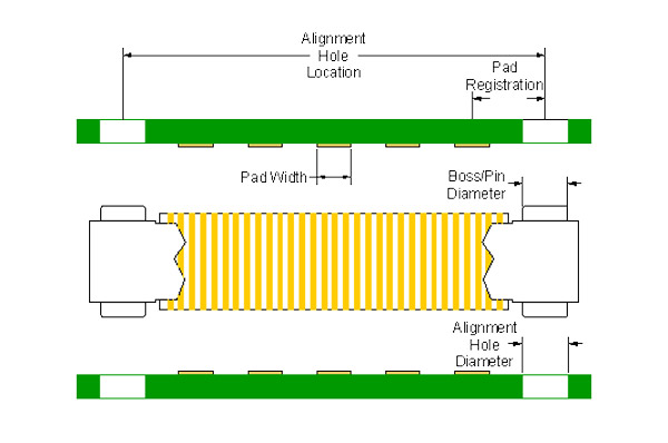
Regardless of your alignment technique, certain factors will still affect the registration of the mating contact pads, and therefore affect the performance of the elastomeric connector in your system. As a result, the tolerances for each of the features shown below should be held as tightly as possible.
Recommendation: undersize the diameter of one set of alignment pins to allow for tolerances in the alignment hole location, alignment hole diameter and the alignment pin diameter to ensure that the pin will in fact mate with the thru hole.
Problem:
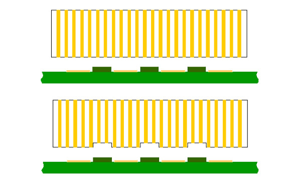
When designing an elastomeric connector into your system, be careful to keep the contact area clear of solder mask. The contact area includes between contact pads and anywhere around the perimeter of the pads that could interfere with the connector housing seating properly.
Possible Solution:
If your PC Board has already been designed and solder mask is present and is higher than the level of the contacts, Z-Axis is still able to overcome this problem. As seen to the right, Z-Axis can create a stepped connector that is capable of making reliable contact even under these conditions.